|
<< Click to Display Table of Contents >> DrizAir 1200 Instructions |
  
|
|
<< Click to Display Table of Contents >> DrizAir 1200 Instructions |
|
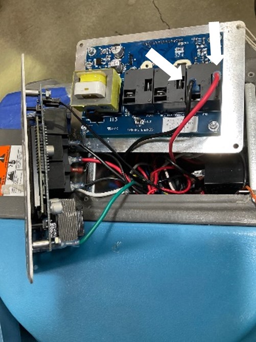
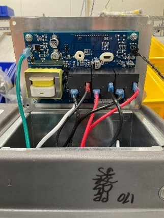
DrizAir 1200 Instructions #3 Control Panel With Grey Lead Wire at RL3 Relay and No Green Lead Wire at Bottom of Control Panel |
|||
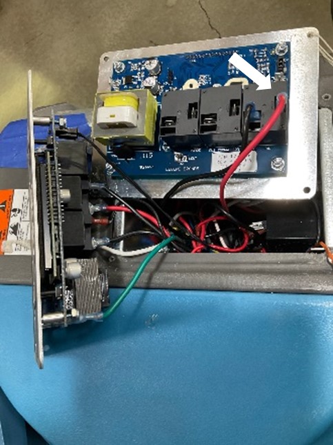
1. Remove the grey lead wire from the RL3 relay on the original control panel, further instructions for the grey lead wire will be provided later.
2. Move the red lead wire from the RL3 relay vertical contact on the original control panel to the vertical contact on the RL3 relay on the new control panel.
3. Move the black lead wire from the RL3 relay horizontal contact on the original control panel to the only horizontal contact on the RL3 relay on the new control panel.
Note: The 3 relays on the PCBA are identified with white text: RL1, RL2, or RL3.
|
|
||
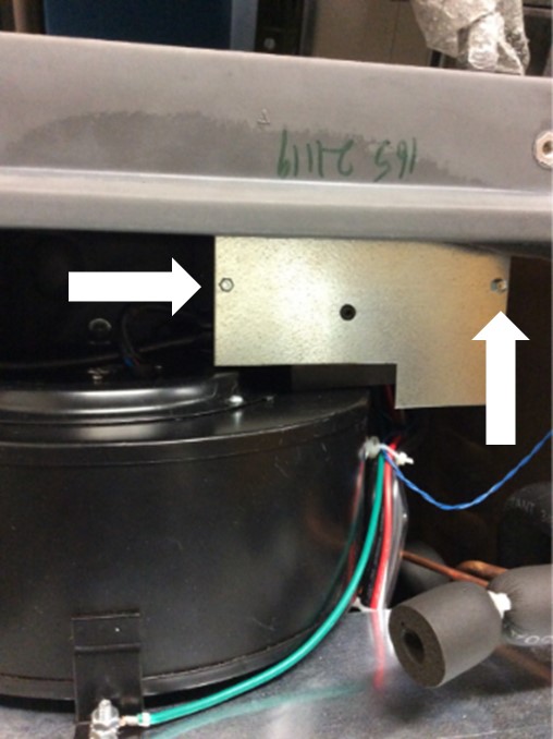
4. Remove the two 1/4" screws that secure the lower panel to the electrical box using the 1/4" socket so that the lead wires attached to the terminal block can be accessed.
|
|
||
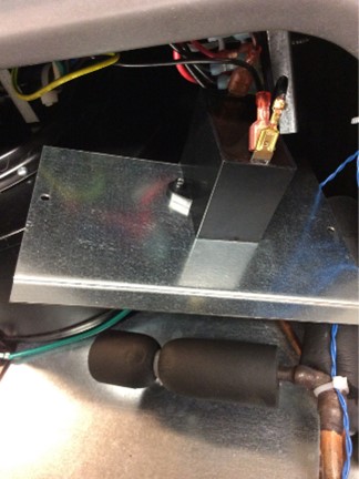
5. Some of the control panels with the additional grey wire attached also have a capacitor installed on the electrical box front panel (as shown in the photo). To access the lead wires on the terminal block in the electrical box, raise the control panel assembly up enough to pull the lower panel from the electrical box.
Note: Older DrizAir 1200 units without a blower capacitor will have a black lead wire from the blower that attaches directly to the RL3 relay on the control panel.
|
|
||
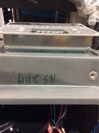
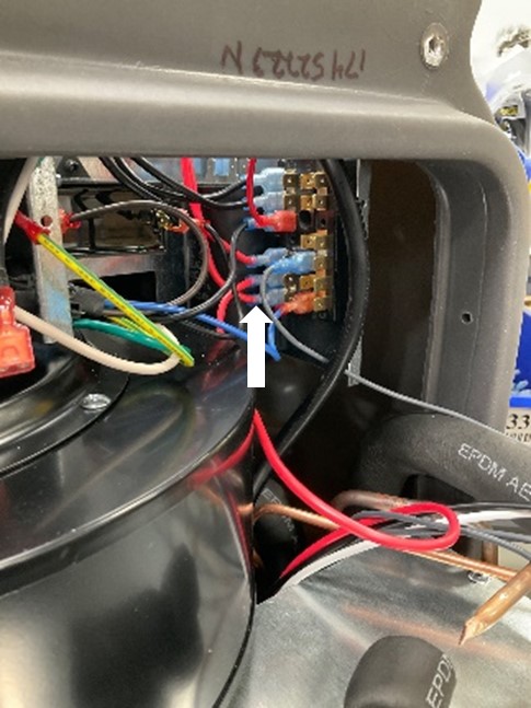
6. Follow the lead wire attached to the vertical contact on the RL3 relay down to the terminal block inside the electrical box. |
|
||
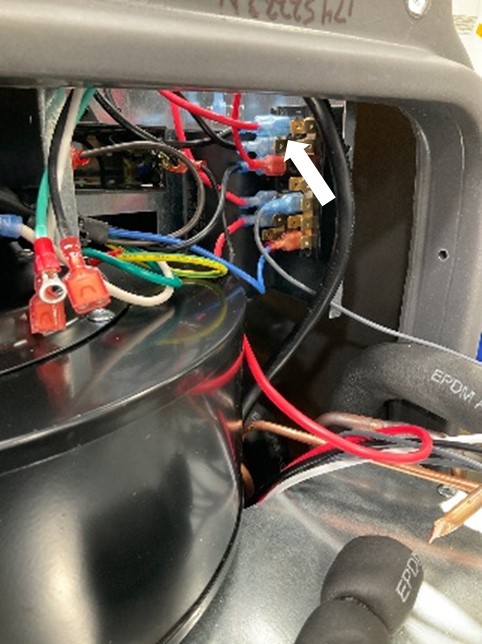
7. In the electrical box move the terminal at the end of the red lead wire from the terminal block group with red lead wires to an available terminal where the group of black lead wires are located.
Note: Not all lead wires attached to the terminal block are shown in the photo. Some components in the photo may vary from actual components in the unit.
|
|
||
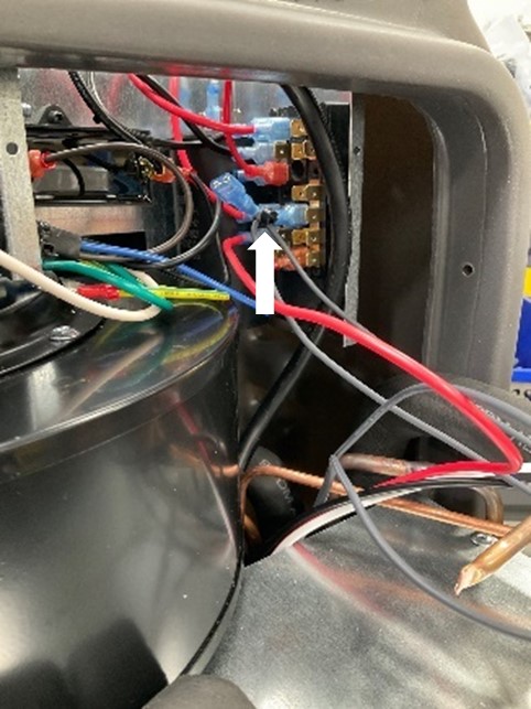
8. Secure the grey lead wire that had been removed from the RL3 relay horizontal terminal and secure it to the other grey lead wire attached to the terminal block with the 6” cable tie provided. The grey lead wires are attached to a solenoid that is no longer needed. |
|
||
9. Continue removing the remaining lead wires attached to the original control panel and reattach them to the new control panel at the equivalent locations. You may need to use needle nose pliers to remove the terminals attached to the original control panel relays. |
|
||