|
<< Click to Display Table of Contents >> DrizAir 1200 Instructions |
  
|
|
<< Click to Display Table of Contents >> DrizAir 1200 Instructions |
|
DrizAir 1200 Instructions #2 |
|||||
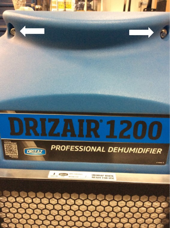
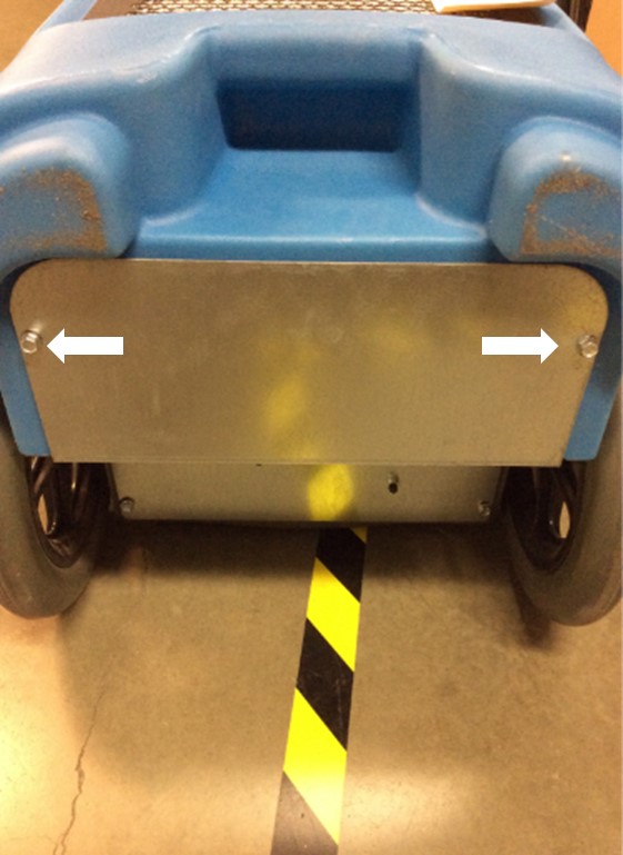
Using a ratchet and 3/8" socket, remove the six bolts that secure the front cover of the unit. Note: Longer screws may require a ratchet extension. |
|
||||
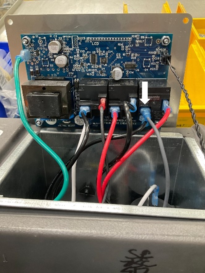
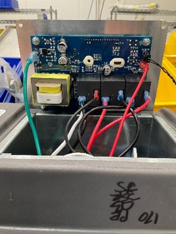
If the control panel includes the grey wire attached to the RL3 relay and no additional green lead wire attached at the bottom of the control panel as shown in the photo, skip to DrizAir 1200 Instructions #3.
Note: Identify relays using the white text, RL1, RL2 or RL3, printed below them.
|
|
||||
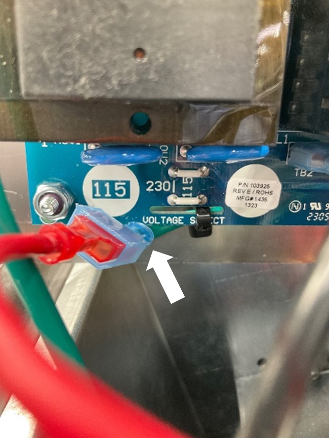
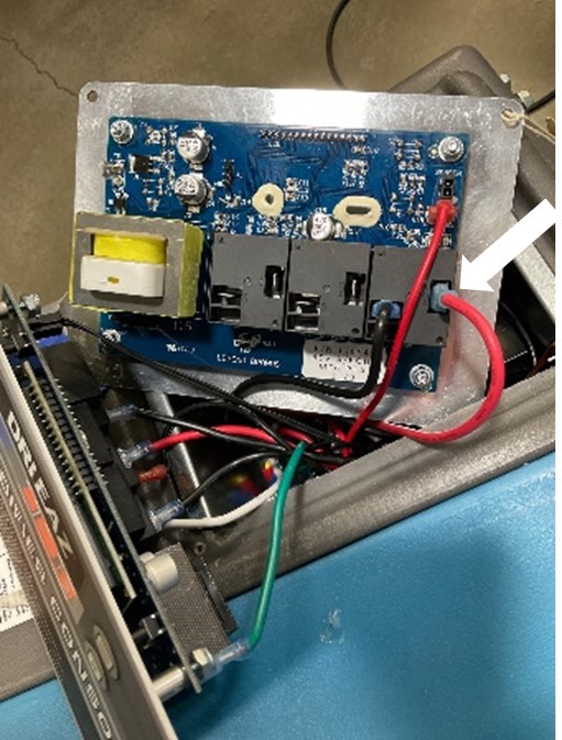
If the control panel includes an additional green lead wire at the bottom of the control panel with a red lead wire attached to it (as shown in the photo), continue with these instructions.
Note: It is uncommon, but if there is a green lead wire at the bottom of the control panel and there is no red lead wire attached to it, skip to DrizAir 1200 Instructions #3.
|
|
||||
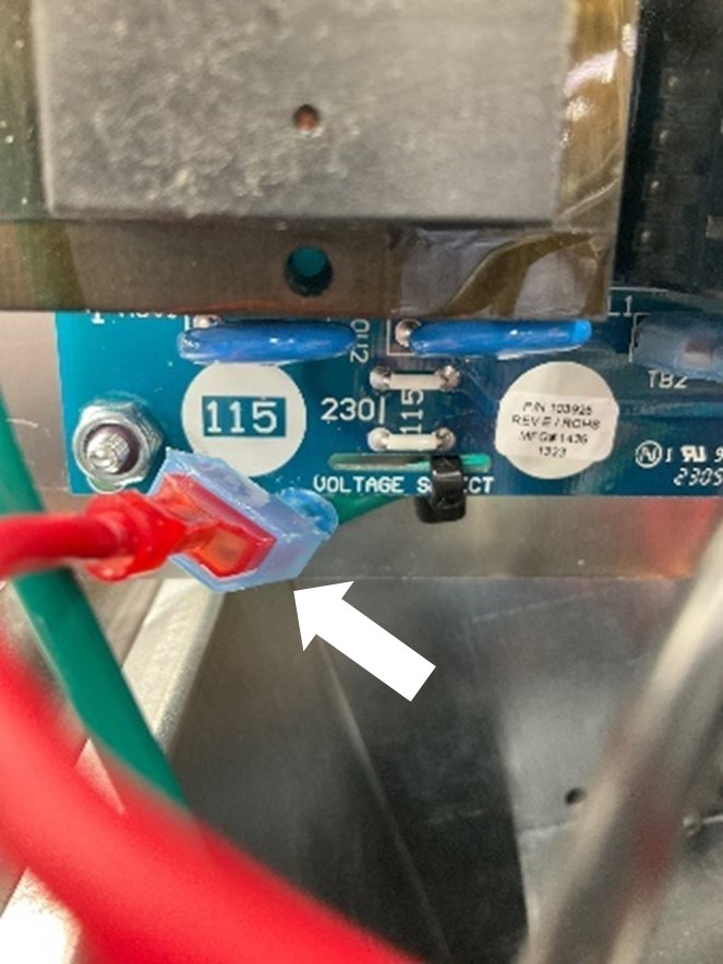
1.Remove the red lead wire connected to the additional green lead wire. |
|
||||
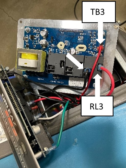
2. Reattach the lead wires on the new control panel at the locations shown in the photo.
3. Move the red pump lead wire that was attached to the green lead wire at the bottom of the original control panel to the TB3 terminal.
4. Move the red lead wire from the vertical RL3 relay terminal on the original control panel to the vertical RL3 relay terminal on the new control panel.
5. Remove the grey lead attached to the RL3 relay horizontal terminal from the terminal and leave it disconnected until later in the process.
6. Move the black lead wire from the horizontal terminal on the RL3 relay of the original control panel to the only horizontal terminal on the RL3 relay on the new control panel.
|
|
||||
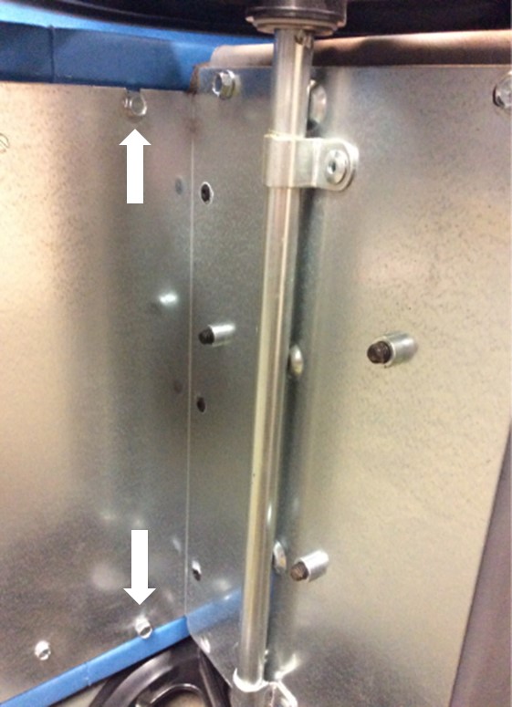
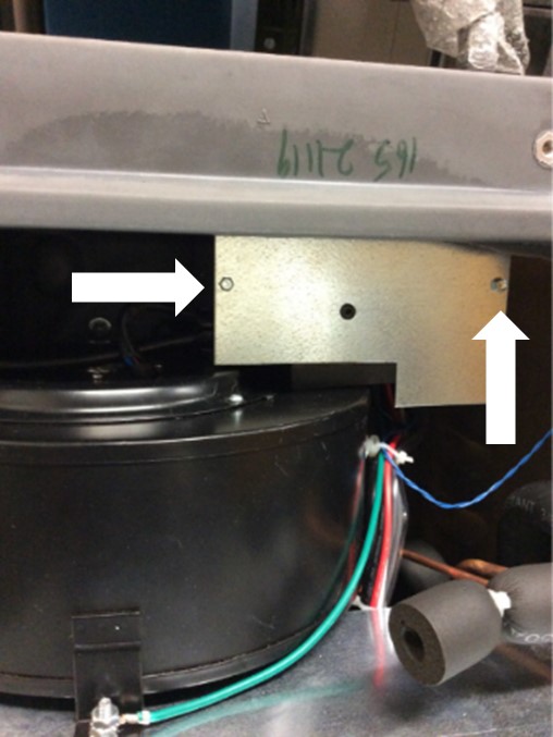
7. Remove the two 1/4" screws that secure the lower panel to the electrical box using the 1/4" socket to access the lead wires attached to the terminal block. |
|
||||
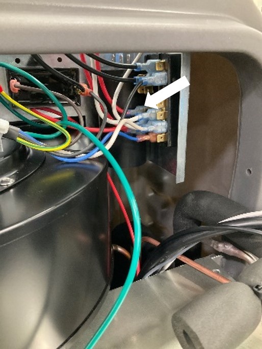
8. Follow the red lead wire attached to the vertical contact on the RL3 relay down to the terminal block inside the electrical box. |
|
||||
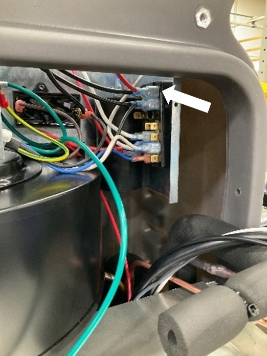
9. Move the red lead wire coming from the RL3 vertical contact from the terminal block group with red lead wires to an available terminal where the group of black lead wires are located.
Note: Not all lead wires attached to the terminal block are shown in the photo. Some components in the photo may differ from actual components in the unit.
|
|
||||
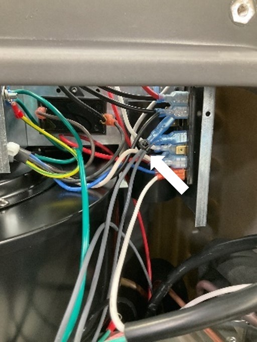
10. Secure the grey lead wire that had been removed from the RL3 relay horizontal terminal and secure it to the other grey lead wire attached to the terminal block with the 6” cable tie provided. The grey lead wires are attached to a solenoid that is no longer needed. |
|
||||
11. Continue removing the remaining lead wires attached to the original control panel and reattach them to the new control panel at the equivalent locations. You may need to use needle nose pliers to remove the terminals attached to the control panel relays.
Skip to Reinstalling Control Panel and Testing Pump to reinstall the electrical box front panel and control panel and test pump functionality.
|
|
||||