|
<< Click to Display Table of Contents >> Evolution Instructions |
  
|
|
<< Click to Display Table of Contents >> Evolution Instructions |
|
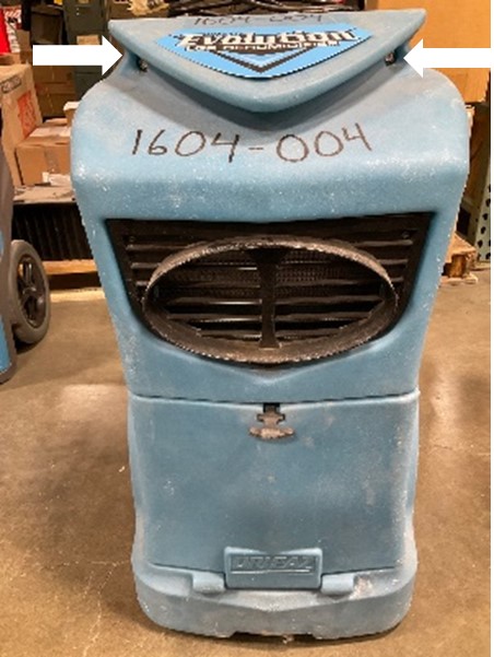
Evolution Instructions #2 |
|||||
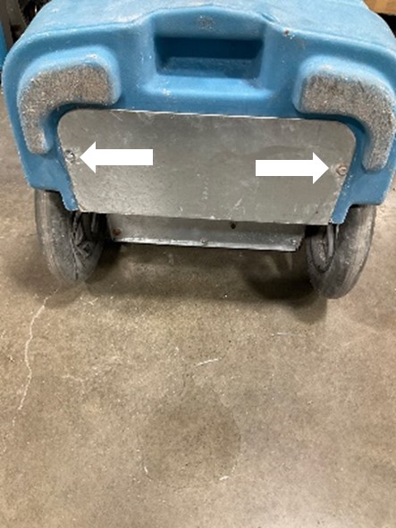
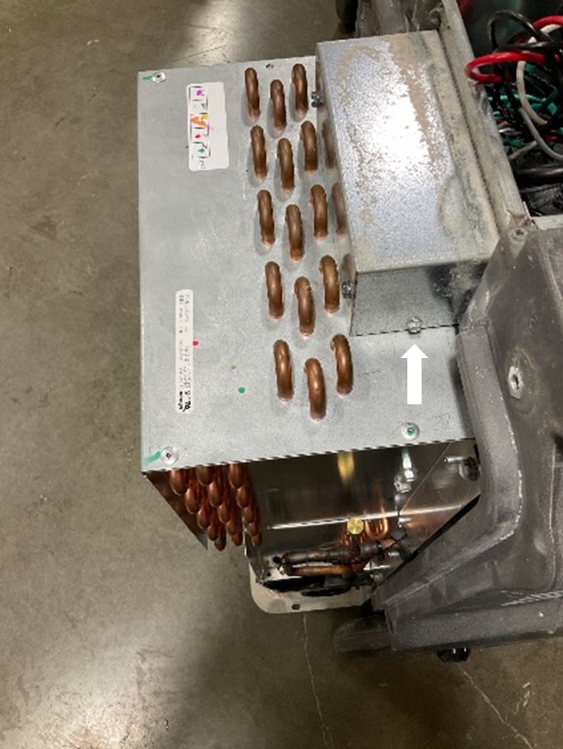
Using a ratchet and 3/8" socket, remove six bolts to allow the front cover of the unit to be removed.
Note: Longer screws may require an extension with the ratchet.
|
|
||||
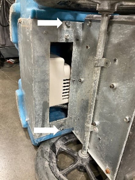
1. Remove the two 5/16” screws on the front of the electrical box and the two ¼” screws on the side of the electrical box cover.
2. Lift the cover off to access additional wiring connections. |
|
||||
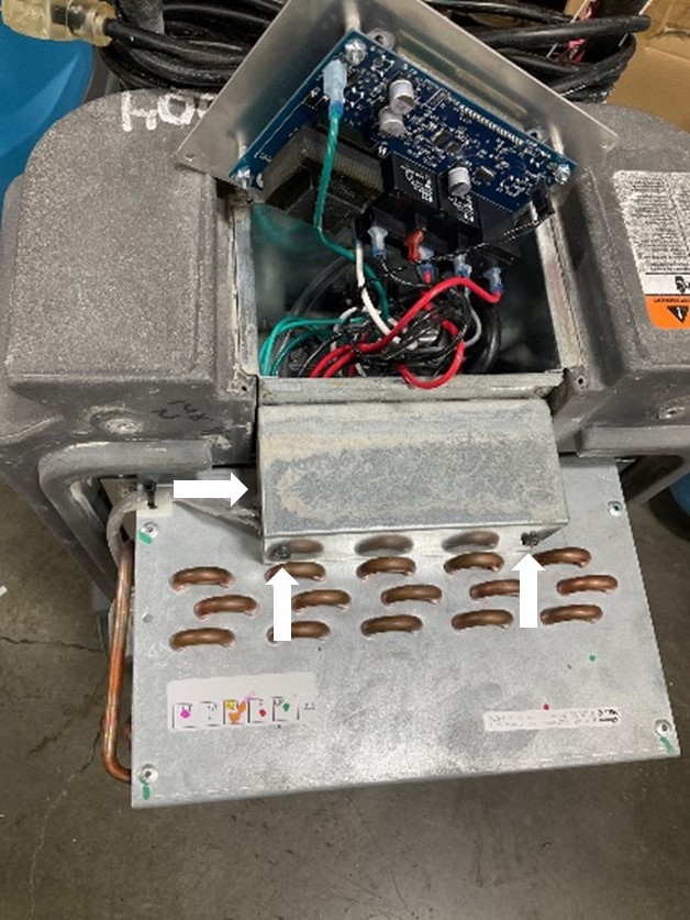
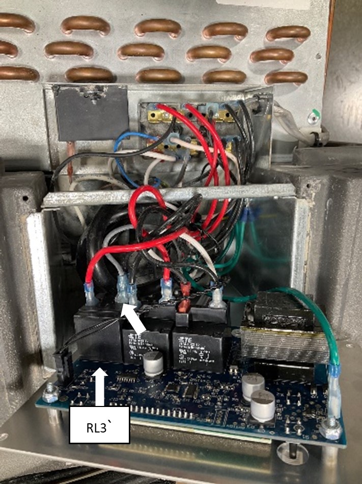
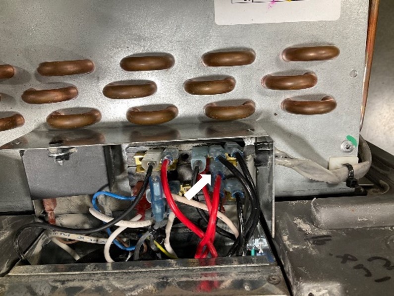
3. Remove the grey valve lead wire from the RL3 relay and secure it to the other grey valve lead on the terminal block with the provided 6” cable tie. The grey lead wires are attached to a solenoid that is no longer needed.
Note: Identify relays using the white text, RL1, RL2 or RL3, printed below them.
|
|
||||
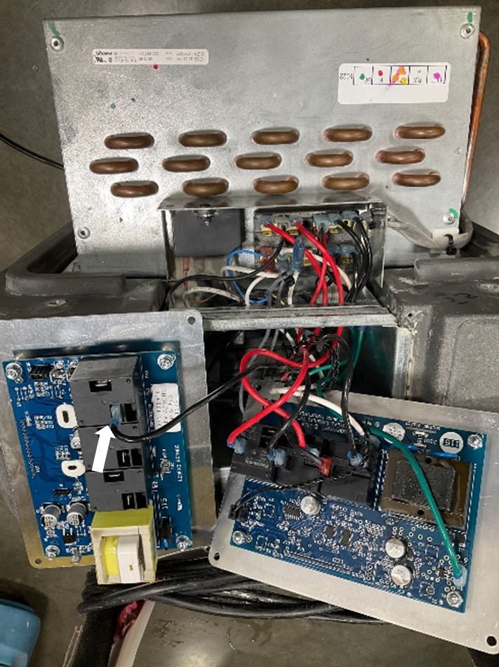
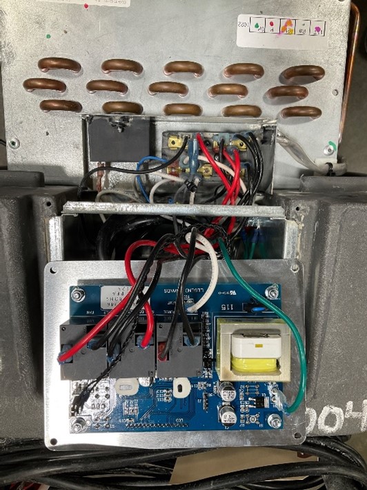
4. Remove the black lead wire attached to the horizontal contact on relay RL3 of the original control panel and move it to the only horizontal contact on relay RL3 of the new control panel. |
|
||||
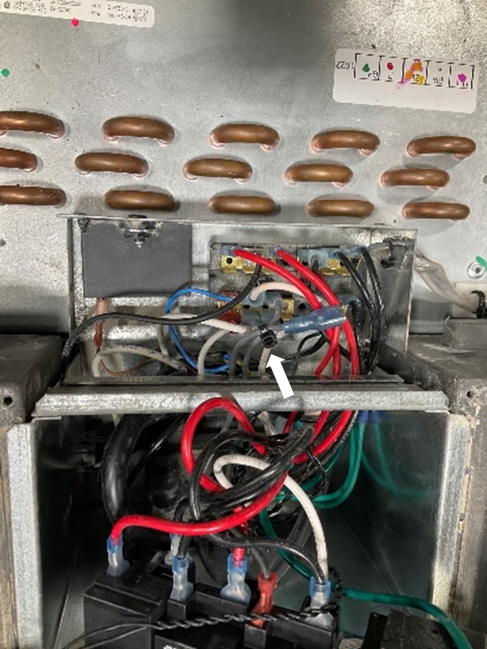
5. Trace the red lead wire attached to relay RL3 on the original control panel back to the electrical box terminal block. Move the red lead wire end attached to the terminal block to the group of terminals on the terminal block with red and black lead wires attached. |
|
||||
6. Move the remaining lead wires attached to the original control panel to the matching locations on the new control panel. It may be necessary to use needle nose pliers to remove the terminals attached to the original control panel relays. |
|
||||
7. Reattach the electrical box cover and secure the control panel in place with the four screws. |
|
||||